Topics

Showing posts with label shaders. Show all posts

Sunday, March 16, 2014

Fly Me to the Moon

Long time no post. I've been busy with my indie game project for the past year, so Project Eden is taking a back seat. However, I recently had to update my old scene files for someone, so I decided to take a closer look at how I created our Earth's natural satellite - the Moon.

This is not quite a "making-of" post, but I do want to bring up a few points. Firstly - gamma correction (and indirectly, linear workflow). When I started playing with CG from the mid-90s to early 2000s, I had no concept of non-linearity or gamma. I lit my 3D scenes within whatever 3D program I used (mostly LightWave back then) and the render output was usually the final product.

Here's an image of a typical Lambert shaded surface. The image on the left is the original rendered output. However, if those calculated pixel intensity values are meant to correspond to real world intensities, the image on the right is more visually correct:


Consider a simple gradient from 0 to 1, where 0 is black and 1 is full intensity white. Logically, 0.5 should naturally appear as 50% gray. This is indeed the case for computer users because all display devices have been "corrected" to work this way.

We call it a "correction" because in reality all display devices are non-linear (50% input signal strength will not give 50% output), and our eyes are also non-linear (we are more sensitive to low light levels and less so at brighter light levels). To our eyes, we would see a large intensity jump between the values of 0 to 0.1, and an input value of 0.5 will appear to our eyes to be more like a 0.7 or 0.8.

The problem only really becomes important when we are trying to create photorealistic renders. We need to compensate for any gamma corrected input into the CG pipeline by removing any existing gamma correction (generally 2.2 for PC displays and JPEG images, and 1.8 for Mac displays), so that all working data are properly linear.

In summary: in the real world, light works linearly. Our eyes however, perceives light intensity in a non-linear fashion. Display devices also outputs intensity non-linearly from their input. Hence, the existence of a whole bunch of gamma corrections working behind the scene of every computer screen, digital camera and JPEG image - all so that we humans can use Photoshop and RGB values in an intuitive and consistent manner. But when we are simulating physical light for photorealistic 3D renders, we need to remove such gamma correction while working within the CG lighting environment, and add it back at the final stage just before outputting to a display device.

In short: all computer rendered images should have gamma correction added if the CG lighting is to behave anything like their real world counterparts. While this is true, the workflow is not quite as simple as that.

If you find what I said confusing, here's a good explanation.

Looking back at the Lambert spheres above, given the calculated output intensities, the image on the right is what our eyes would see if those intensities correspond to brightness values in reality, even though the image on the left may look more aesthetically pleasing.

Next, I would like to consider diffuse shaders. Traditionally, the diffuse shading aspect of a typical CG material would be a Lambert shader, and the specular shading aspect would be Phong or Blinn. In the on-going quest for photorealism, the industry defaults are now Oren-Nayar for diffuse and Cook-Torrance for specular. Both are more computationally intensive but give results that better matches real world materials.

The Oren-Nayar shader has a roughness component which allows us to emulate matte materials such as chalk and clay much better than Lambert can. Below are some comparison images between Lambert and Oren-Nayar, and at different gamma values:


So what do all these technical stuff have to do with the Moon? Well, firstly the Moon surface is not simply Lambertian. When was the last time you saw darkening at the edges on a full moon night? Never! We know the Moon is actually spherical, but it still appears quite flat because of the way it's surface scatters sunlight. We can simulate it's roughness and light response better using an Oren-Nayar shader.

Secondly, we need to add gamma correction to the rendered output so we can see the CG rendered intensities as our eyes would. Thankfully, Houdini's built-in image display utility "mplay" defaults to a gamma of 2.2, so if you are using Houdini you should already be seeing gamma corrected output.

Thanks for reading. Here's the CG Moon:


Enjoy!

Friday, October 18, 2013

Noising up a texture procedurally

When applying texture to a CG surface, there are two basic options:

1) Texture mapping - using an image map to define the patterns
2) Procedural textures - using a mathematical algorithm to define the patterns

Naturally there are pros and cons to both methods. The first affords maximum artist control but incurs a memory and resolution limit. When you zoom in on an image texture too closely, it loses detail and becomes blurry. Procedural textures do not have this problem, but they are much more difficult to art-direct and may require programming skills beyond the more artistically inclined user.

With Project Eden there is really not much choice except to go with option 1. Even though fractal terrain generation and rendering has come a long way, the Earth has a highly recognizable face thanks to NASA photo imagery, so a purely procedural approach can be easily spotted.

I'm going to describe a method which can be used to push the image texture resolution limit a little further by making use of procedural noise. Typically, a CG texture artist would add noise to the color, diffuse, specular or bump channels, but we'll be doing something different today.

Here's a flat plane mapped with a grid image:


Here's the same grid with noise added. Notice that the grid pattern has been distorted procedurally, without needing to increase the resolution the original texture:


More noise can break up the pattern even further:


By now, some of you would have probably guessed how it's been done. Instead of adding noise to the pattern, we add noise to the UV lookup coordinates, so each texel lookup will return information that is offset from where it should be. Here's the Houdini shader network used:


You can see that a bit of turbulent noise has been added to each UV coordinate before being passed into the texture lookup node. The noise is based on surface position so it is independent of the resolution of the texture image.

Hence, we can use this simple trick to add more "resolution" to our image textures. A relatively inexpensive technique without the need for fancy Photoshop filters or edge detection algorithms. The results are especially applicable for naturalistic patterns, not so much for mechanical patterns. Now go out there are make some noise! ^^;;
 
Pixel art of world map found on the internet
Same pixelated texture reference by noisy UV lookup

Sunday, September 9, 2012

Making of a Planet - Part 4 - Simple atmosphere shader


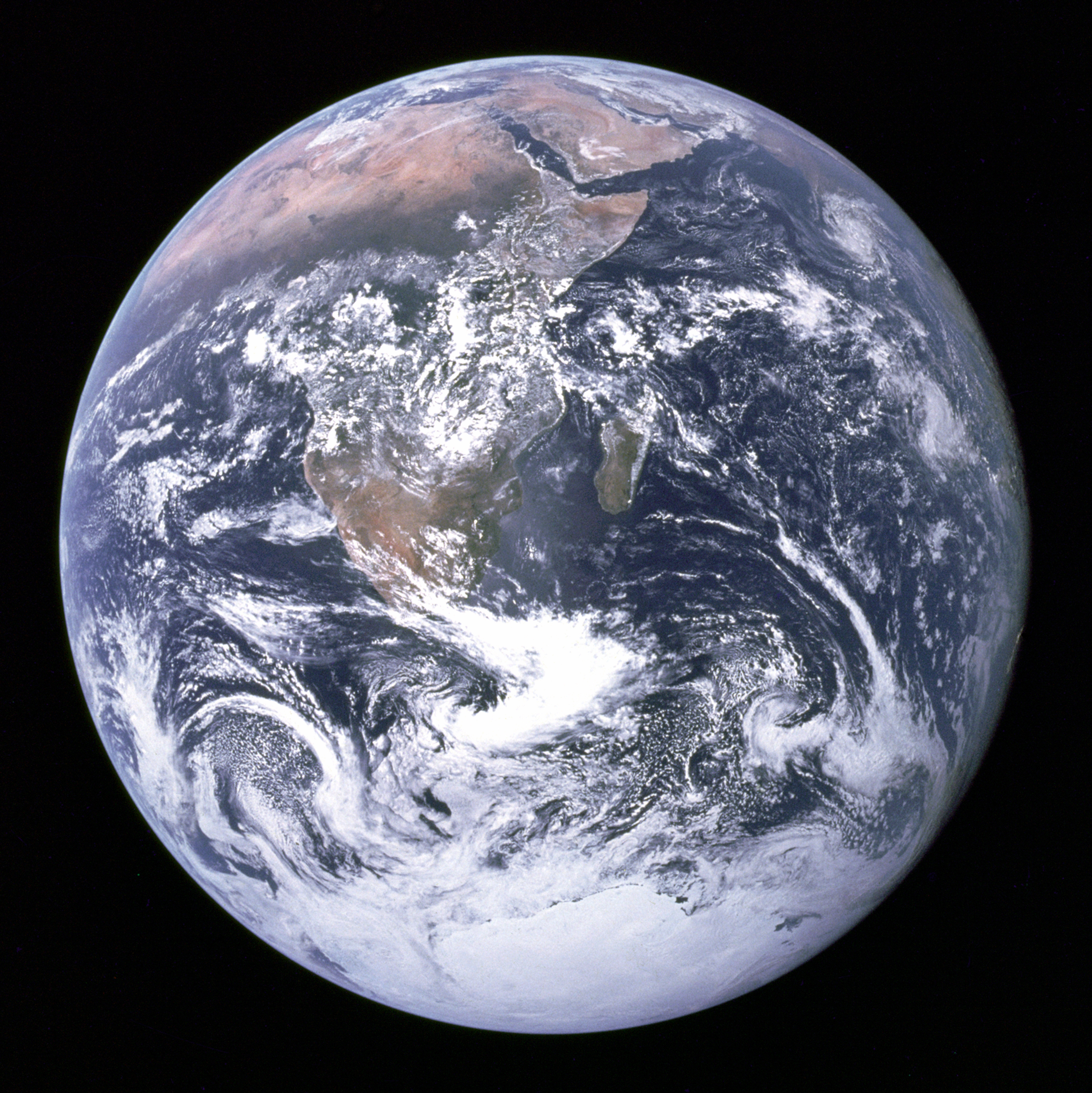
Here's a good place to start if you need some instant texture maps for creating a CG Earth: JHT's Planetary Pixel Emporium. The color, bump and specular maps are self-explanatory, although in my case I'm using true displacements instead of bump. You can also get the Blue Marble textures from NASA's Visible Earth here.

The tricky part is to create the Earth's atmosphere. From reference photos, we can see that due to the curvature of the planet, the atmosphere appears more visible along the circumference compared to the center.


To achieve this effect, we can make use of the facing ratio of the surface toward the camera. Referring to the diagram below, when the view vector and the surface normal is in line, the facing ratio is 1, when they are perpendicular, the facing ratio is 0. Surfaces that face away from the camera are not rendered, so need not be considered. As such, the facing ratio at any point always fall between 0 and 1:


There are different ways to obtain the facing ratio. Maya has a very useful Sampler Info utility node which will provide that information. In Houdini, it is simple to build using the Eye vector (I) and the surface Normal vector (N). Just do a dot product, which will give you the cosine of the angle between them as long as the vectors are normalized. When the angle is 0° (I aligned with N), the cosine is 1. When the angle is 90° (I perpendicular to N), the cosine is 0°. Remember to normalize both N and I, and also, since I is the direction from Eye (camera) to the surface, it has to be negated. Finally, an Absolute node is used to ensure that the output values are positive. The SHOP network is shown below:


The network above will shade any object as if there is a headlight attached to the camera (surfaces facing the camera are brighter and surfaces facing away are darker). From there, we will adjust the output into a suitable type and range using a bit of math. The diagram below illustrates what we are trying to achieve:


The following SHOP network does exactly the above:


The Complement node inverts the black and white facing ratio, and the Power node (exponent of 6 used in this example) adjusts the intensity. A Constant of type "color" set to a suitable shade of blue is multiplied with the output of the Power node to get the blue tinted version, which is then output as the Surface Color. The output from the Power node is fed into the Surface Opacity output to allow for transparency.

Let's apply this shader to a new sphere object slightly larger (1% larger in this example, using a uniform scale factor of 1.01) than the original Earth sphere :


Of course, this is just a starting point. There is immediately the problem of the atmosphere being lit even along the shadowed side of the Earth. This is easily remedied by multiplying the output color by a shadow term, or by a self-shadowing diffuse shader such as Lambert:

The example below uses a Lambert diffuse intensity of 2

While this is more physically correct, the previous unshadowed version looks aesthetically more pleasing, which is why many planetary artists invoke artistic license to bend the laws of physics. Alas, our goal is photorealism, so we will stick with the correct look for this kind of exposure levels. Just remember it is a viable option because the stars (and sometimes the Moon) always provide faint illumination to the night side of the Earth.


Wednesday, August 15, 2012

Shader upgrades ^^

Necessity can be a great motivator. A recent freelance opportunity meant I had to create much faster shaders to get the job done in time. I dove head first into VEX code writing for the first time, and managed to adapt Sean O'Neil's real-time atmospheric scattering algorithm into my new Earth shaders.

My method uses the CPU instead of GPU and is not real-time, but is still multiple times faster than my old method while looking visually very similar. Some volumetric shadow effect is lost, but not really noticeable if you are not looking for it, and the amount of speed up is well worth tradeoff.

Naturally, the implementation is not straightforward and took me almost 3 days to get it working properly. Perhaps I'll post more details under the "making-of" label in future.

Making of a Planet - Part 3 - Shader Basics

In this post I'll be describing what I learnt about shaders when building the CG Earth, with specific examples of Houdini VEX shader networks. First off, a quick introduction to how shaders work.

What are Shaders?

Shaders can be thought of a set of program instructions that tells a renderer how to determine the color of a surface (or volume) at any given location. In 3D programs, they are also referred to as materials.

Shaders are actually program code written in a shading language. However, Houdini allows the code to be build visually as a node network (called a SHOP network, for SHader OPerators). The most famous industry shader language for rendering CGI is the RenderMan shading language. For real-time graphics (e.g. games and 3D applications) you will hear names like GLSL and HLSL. Houdini's shading language is called VEX (Vector EXpressions).

Regardless of shading language used, the simplest shader returns a constant color at every point, making the object appear uniformly flat. In the following example, a constant color blue is being fed into the surface output of a Material Shader Builder node in Houdini's SHOP network:

The constant shader instructs the renderer...
 ...to use the same color for every point on the surface

Let's consider how light may affect how the surface looks.

The following example is the basic Lambert shader (which mathematically is the dot product of the normalized surface normal vector, N, and the normalized light vector, L). It's amazingly elegant that this single dot product formula is enough to describe how the light falls off a surface depending on its angle to the light source:

A classic Lambertian shader...
...makes the teapot surface react correctly to light

Lighting Inside a Loop

In Houdini, this lighting calculation must take place inside what is called an illuminance loop. A loop in computer programming is a sequence of instructions that repeats itself until particular conditions are met. Think of it as repeatedly calculating the same lighting formula (dot product) for all the points on the surface that appears in the final image, using the corresponding N and L vectors for each point location.

So we now have a properly lit teapot, but what if we want it in blue color? All we need to do is to multiply the result of the illuminance loop with a constant (blue color) before passing it to the output:

The Lambert shading network from before is actually hidden inside the illuminance loop node above
Only one dot product and one multiplication is needed to get this blue teapot

Houdini already includes a selection of basic CG shaders (such as Lambert) as a network node so we don't really need to create our own illuminance loops. However, writing your own illuminance loop function allows specific low-level control over the look of your material. For the Earth shader, I adapted a light wrap shader inside the illuminance loop to simulate atmospheric scattering.

Building Visual Complexity

When shaders take into account various factors such as lighting and texturing, more complex looks can be achieved. Notice also how we can take the first two separately rendered images (the constant blue and the grayscale lit teapots) and combine them using a multiply blending in a 2D program to get the same results (blue lit teapot). Therein lies the flexibility and power of render passes and compositing, because we can tweak the amount of blending without having to re-render in 3D.

The example below is a slightly more complex shader including specular highlights and texture mapping, but the basic concept is the same as the previous examples. Notice that the texture map (diffuse color) is multiplied with the Lambert shading, and the specular is added to the results.

No illumination loop used here
More complex shaders will result in more realistic surface appearance

Shader writing may not be everyone's cup of tea, but with some effort anyone can write their own shader. There's a definite amount of mathematics and logical thinking involved, but with it comes the power to go beyond what is available off-the-shelf.

If you're keen to find out more, I recommend the following books:

1) Texturing and Modeling: A Procedural Approach
2) The RenderMan Companion: A Programmer's Guide to Realistic Computer Graphics
3) Advanced RenderMan: Creating CGI for Motion Pictures

That's it for today. Next post I'll elaborate more about my Earth shaders.